DESIGNED - MANUFACTURED
ASSEMBLED & PACKAGED
IN THE U.S.A.

the One and Only
     Genuine...

- CROSS OVER & TRACK BAR SYSTEMS -

Measuring for your steering system will insure you the absolute best fitting product possible. These short easy steps will insure you get the exact sytems and eliminate factory variances which can be up to 3/4" off due to the axle tube being pressed in different depths.

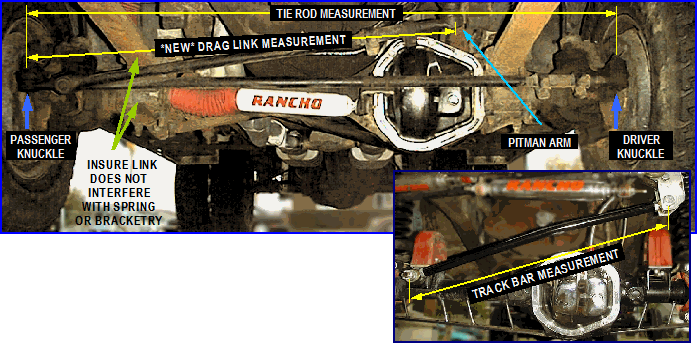
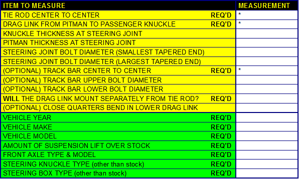
With the wheels centered straight ahead, measure the tie rod from knuckle to knuckle, at the center of each bolt. Do NOT measure the grease fittings. If you have a side to side mounted drag link equipped vehicle (as above), then measure the distance from the passenger side knuckle to the pitman arm, at the center of each bolt. Do NOT measure the existing drag link, since the new one will be mounting in as new location on the passenger knuckle. Even if you have what appears to be a perfectly aligned vehicle, you can maximize the performance of your Bullet Proof Steering System by insuring your front end is accurately aligned and that your steering box is centered within it's travel to provide maximum lock to lock travel in both directions before measuring and ordering your system. To check this, LOOK HERE.

Then measure the thickness of the
knuckle height, and the pitman or steering arm to get you the correct length bolts. Find the largest diameter of the tapered hole where the tie rod fastens. Insure that the front end alignment is correct, so that accurate measurements will be achieved.

To measure the
track bar, measure from the center of the upper track bar bolt to the center of the lower track bar bolt. Not all vehicles have track bar, and those do not need this feature. For a track bar equipped vehicle not having a track bar present, and with the wheels centered straight ahead, measure the track bar mounts from hole to hole, at the center of each bolt. Insure that the front end side to side alignment is correct, so that accurate measurements can be achieved.

If you need a custom designed and bent track bar, submit a full scale template as described on this page SEEN HERE.

If you are reasonably sure your current linkage and front end is lined up correctly, then measure guide as ILLUSTRATED ABOVE. If your linkage is bent or non-existent, then LOOK HERE. If your vehicle is on jack stands or the front end is out, then LOOK HERE. If there is no track bar in the vehicle and wish to measure for a new one, then LOOK HERE.

We find it best to design our steering with as much of the threads engaged for both strength purposes, as well as allowing for maximum adjustment in case the tie rod gets bent in an off road situation, where the ends can be adjusted outwards to get back on the trail again. So, make the necessary compensations for potential errors (too long, too short) when providing your exact measurements upon ordering.

TYPICALLY YOU'LL HAVE 1-1/8" OUTWARD ADJUSTMENT & 1/8" INWARD ADJUSTMENT please consider this and compensate your measurements you provide us accordingly
The purchaser is solely responsible for all correct measurements, clearance, fitment and feasibility considerations. No returns on incorrectly provided specifications or measurements. Replacement costs are the sole responsibility of the purchaser.

These components are intended for off highway applications only

HOW TO MEASURE FOR A CLOSE QUARTERS BEND (tie, drag & track bars)

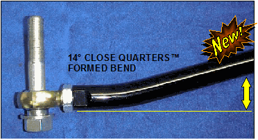
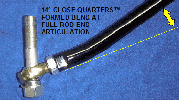
...while bending tubing is the last resort, sometimes it is necessary to fit a particularly unique application. Keep bends to a minimum and as close to the rod end as possible to minimize lateral adverse pressure on the rod end as well as leverage force on the bend in the tubing. Utilizing larger tubing options and upgraded rod end strengths is recommended for maximum performance and safety...

1.  Take a string and run a straight line between
      the two connection points, usually from the
      pitman arm to the steering knuckle.
2.  With an angle finder, determine the angle of the
      string to the ground, which represents the
      location of the new drag link.
3.  Consider the angle of the knuckle surfaces where
      the rod end will sit & calculate the tubing bend
      that will be required to correct rod end angle.
4.  Keep in mind the downward travel as to not allow
      the bent tubing to contact the tie rod under full
      suspension compression.
5.  It is not recommended to exceed 14 degrees of
      bend to reduce lateral pressure at the rod end ball
      rather than the desirable straight on "push and
      pull" forces the rod end is designed to operate
      under.
Both ends of the tube can take advantage
     of close quarters bends with no decrease in
     strength as compared to just one end bent.
     
Provide your required angle to us.
7.  The customer is responsible for all engineering
      and strength considerations of their request.

These special Close Quarters pressure formed bends minimizes stress on the bar, loosing very little in overall strength. To create these very tight and compact formed bends so close to the end requires additional machining and milling work as well as additional hand labor to get this bend as close to the end as possible. In doing so, there is much less leverage and stress placed on the tubing itself. The end result is a much desired benefit without the sacrifice in structural strength or increasing operating fatigue. A Bullet Proof exclusive!

ABOVE OPTIONS REQUIRE UPGRADE TO STAGE-II EXTREME DUTY ROD ENDS FOR MAXIMUM STRENGTH